
- 298
- 6 242 987
Lewis Loflin
United States
Приєднався 30 бер 2008
Hello and welcome. My channel is mostly electronics projects. My website and videos cover a broad range of electronics and micro-controller projects for advanced and beginning hobbyists.
Program Code Arduino CCS H-Bridge Motor Control
The code starts at 3:45. Part 1 ua-cam.com/video/MO455DKJ9X4/v-deo.html
www.bristolwatch.com/ele5/index0.htm
www.bristolwatch.com/ele5/index.htm
www.bristolwatch.com/ele5/index0.htm
www.bristolwatch.com/ele5/index.htm
Переглядів: 663
Відео


Arduino CCS H-Bridge with Large DC Motor
Переглядів 67714 годин тому
Focus on braking, speed, and direction control. Based on earlier projects. Programming is the next video. www.bristolwatch.com/ele5/index0.htm www.bristolwatch.com/ele5/index.htm

Arduino Battery Charger uses CCS and TL431 Comparators
Переглядів 85114 годин тому
The culmination of several previous circuits. Includes Arduino code. See the following links: www.bristolwatch.com/ele5/index0.htm www.bristolwatch.com/ele5/index.htm www.bristolwatch.com/ele5/tl431_sink.htm
3 Bipolar Transistors in Parallel and Other Issues
Переглядів 1,2 тис.4 місяці тому
3 parallel transistors for a 20A battery charger constant current source. How DC gain shifts with collector current. www.bristolwatch.com/ccs/LM317c.htm

How and Why to Connect Bipolar Transistors in Parallel
Переглядів 1,6 тис.4 місяці тому
Better power and stability for a constant current source. Schematics, etc. www.bristolwatch.com/ccs/LM317c.htm
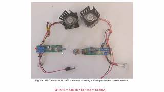
LM317 High Powered Current Source 2024
Переглядів 1,4 тис.5 місяців тому
Updates and additions to an earlier video Adjustable LM317 High Powered Current Source at ua-cam.com/video/n94xqPMhmTo/v-deo.html Webpage: www.bristolwatch.com/ccs/LM317b.htm

Update 2024 ULN2003 Transistor Array Operation
Переглядів 2,1 тис.5 місяців тому
www.bristolwatch.com/ele/uln2003a.htm ULN2003A Darlington Transistor Array with Circuit Examples Unipolar stepper motor driver using ULN2003 driving PNP Darlington transistors. Old video ua-cam.com/video/5k5Li4XRUb4/v-deo.html Arduino Unipolar Stepper Motor Driver Board with Arduino Code ua-cam.com/video/HTVYiLOY8SQ/v-deo.html

TL431 12V Battery Charger Complete
Переглядів 9635 місяців тому
Completely tested and working. Schematics: www.bristolwatch.com/ccs/tl431_ccs4.htm

TL431 Power Constant Current Source Demo 1
Переглядів 1 тис.5 місяців тому
Adding an additional pass transistor for higher current. See www.bristolwatch.com/ccs/tl431_ccs3.htm
TL431 Constant Current Source Circuits
Переглядів 1,2 тис.5 місяців тому
Schematics and images are at the following link. www.bristolwatch.com/ccs/tl431_ccs2.htm
TL431 Under-Voltage, Over-Voltage Detection
Переглядів 6 тис.5 місяців тому
See the following link for details and schematics. www.bristolwatch.com/ccs/tl431_ccs1.htm
18.5V Li-Ion Battery Charger with TL431 (short)
Переглядів 8025 місяців тому
Just the charger circuit operation. Works for 12V batteries as well. www.bristolwatch.com/ccs/lithium_charger.htm
Charging, Charge-Balancing 18V Li-Ion Battery with TL431
Переглядів 1 тис.5 місяців тому
A look into higher-voltage battery charging of Li-Ion batteries with the TL431. www.bristolwatch.com/ccs/lithium_charger.htm
TL431 10-Volt Charger Short Version
Переглядів 1,1 тис.5 місяців тому
Shorter version of earlier video. Just the resistor calculations. www.bristolwatch.com/ccs/lithium_charger.htm
TL431 Battery Charger Circuit Calculations Revised
Переглядів 7175 місяців тому
Revised charge voltage resistor calculations. How and why. www.bristolwatch.com/ccs/lithium_charger.htm
TL431A Lithium-Ion Cell Charging Circuits
Переглядів 1,6 тис.6 місяців тому
TL431A Lithium-Ion Cell Charging Circuits
Switching Power Supply Combined with Current Limiter
Переглядів 2,7 тис.Рік тому
Switching Power Supply Combined with Current Limiter
Transformer High Voltage Connections Tutorial
Переглядів 1,7 тис.Рік тому
Transformer High Voltage Connections Tutorial
Hall Sensor Magnetic Bias Detects Ferrous Metals, Gears
Переглядів 3,7 тис.2 роки тому
Hall Sensor Magnetic Bias Detects Ferrous Metals, Gears
Exploring Omni Hall Effect Sensors with Dual Outputs
Переглядів 7902 роки тому
Exploring Omni Hall Effect Sensors with Dual Outputs
Hall Effect Latches Theory and Circuits Pt. 3
Переглядів 1,4 тис.2 роки тому
Hall Effect Latches Theory and Circuits Pt. 3
Operate, Build Hall Effect Switch Pt. 2
Переглядів 2 тис.2 роки тому
Operate, Build Hall Effect Switch Pt. 2
Basics of Hall Effect Analog Sensors & Switches Pt. 1
Переглядів 3,5 тис.2 роки тому
Basics of Hall Effect Analog Sensors & Switches Pt. 1
How to Connect Transformers in Series-Parallel
Переглядів 35 тис.2 роки тому
How to Connect Transformers in Series-Parallel
IR2110 Based High Voltage H-Bridge Motor Control
Переглядів 27 тис.2 роки тому
IR2110 Based High Voltage H-Bridge Motor Control
High Voltage IGBT H-Bridge Circuit Using Photovoltaic Optocouplers
Переглядів 8 тис.2 роки тому
High Voltage IGBT H-Bridge Circuit Using Photovoltaic Optocouplers
SIDAC Controlled Flashtube and Pulse Circuits
Переглядів 2,9 тис.2 роки тому
SIDAC Controlled Flashtube and Pulse Circuits
Build Autotransformer-Variac AC and DC Power Supply
Переглядів 4 тис.2 роки тому
Build Autotransformer-Variac AC and DC Power Supply
I watched the other video that is associated with this, in which you have an LM317 for current limiting on a separate PCB. Any chance you've looked to convert the pair of circuits to limit current via feedback to the switcher, rather than limiting in a linear fashion?
little correction: 24Vin - 5Vout = 19Vdrop * 0.5A = 9.5W wasted in the 7805, not 10.5W
Lewis, it's always a pleasure for me to see you have posted a new vidéo. I think i found a mistake on the "H" bridge schematic. SW1 is HB1 and SW2 is HB2. Is that right??
Correct. HB refers to the opto couplers; the switches can also exist. They are used for testing. I should have used the opto label.
where in this video is show how motor spin ????? and chose directions also change rpm for motor ????
Hope all is well with you !
I'm OK. Thanks.
Thanks for this episode. This is saved with the previous report.
very cool explanation
Thank you for this report. I will definitely keep this. There is a good chance that I will use it. Thank you and see you next time.
Thanks for sharing Keep up the good work
Nice.
Thanks a lot
At 8:58, the 12V NEG and Arduino GND are connected together, will it hurt the Arduino device, because there's 12 volts potential in the battery versus 5 vots potental in the Arduino device? Will the greater potential (12 volts) will cause a current to flow from 12 v battery to the 5 v Arduino? Or is this a case where ground are cosidered zero votage therefore no current will flow from the greater potential to the lower potential??
No, the Arduino is fine unless the transistor develops a collector-to-base short. I often use optocouplers to prevent noise and short circuits in the Arduino.
In the 24 vdc lamp, and 24 vdc relay with 120 vac lamp examples, is pin 8 ground connected to the 5 vdc ground for the microcontroller inputs, or is it connected to 24 vdc ground?
No. I leave it disconnected for non-magnetic loads, other connect to lam +.
@@LewisLoflin I am using a ULN 2003 to fire a 24v relay, for this application I should connect pin 8 to 24v GND?
I am not understanding what "lam +" is sorry.
@@Austin-d8p Sorry. E is ground, and common goes to +V.
Hi, I doubt it when You say, "you can omit connecting the suppressor diodes common pin when not using indictve loads". I have done exactly that just because of couriosity on my latest clock build. It was on a high side driver. Anyway. IF the diodes could be pulled out of the circuit that would work. By not connecting the common pin to Vcc it makes an OR-gate out ouf the INTERNAL diodes. Watch the multiplexed outputs simultaniously altering when done on a clock. The number digits start blinking at the frequency of the seconds LED, fed through the same chip.
I can't say much until I see a schematic of what you did. Connect the diodes to Vcc then. Thanks for the info.
Hi, see my U125D based clock. Initially it had used an integrate high side driver. The UTC 62783 is suffered from not fully shutting off the unused digits on a multiplexed clock. This results in ghosting on the LED displays. The Toshiba IC TBD62783AP is said not being suffered from this bad behaviour But I had none on hand. I replaced the 62783, a counterpart of the well known ULN2803, with a number of discrete transistor drivers. @@LewisLoflin Works much better.
BURNED, you put 40V for Gate Mosfet plus 50~95V and 40K resistor and 10~19V gate mosfer >, and 10K resistor to emitter via colector GRAND
This won't work at that kind of voltage. The limit is 20V.
BURNED, 40K resistor plus 50V voltage and 10V emitter, and 10K divider resistor to the battery
Great video. In regards to the PNP power transistor used, if I require a higher input voltage of say 200VDC and output current of 8 - 10 amps, could I swap out the single PNP power transistor for a Darlington Transistor? Also the LM317 would be changed to LR8NS
No, unless all polarities are reversed. As for that kind of power I'd recommend not playing around with that.kind of power.
You should be talking about the input levels of the mosfet driver, not the mosfets themselves
Can't thank you enough
can i use mechanical switch instead of optocoupler?
Yes you can, but why?
Hi, man i want to make an h-bridge for arduino but aldo want to control the speed of the motor. There are more questions that i would like to ask about this.
email lewis@bvu.net
hi lewis ,,, good video ,, please how can some one get in touch with you
lewis@bvu.net
@@LewisLoflin thanks so much i send you an email please try to check and see if you can help out
I'm curious what are you powering with this circuit? Are you actually using this circuit for something or this just an academic exercise?
Battery charger, motor current limit, etc.
Newbie here. How can this be adjusted to be current limiting device. I want to test broken motherboards with voltage injection (usually 1 up to 5 volts) but need to protect the motherboard from too much current (100ma to 1000ma range). How would this be achieved ? Can you make video about this?
I like conventional flow!!
The 100 of 100 teaching and clear , good
Thank you.
Thank you @Lewis!
You are welcome.
Thank you so much for sharing🎉🎉🎉
I really dislike schematic representation where input is on the right and the circuit on the left, with no clear separation between input hot/live and the output live wire. Makes schematics hard to read and it is even worse for understanding what the hell it does.
Thanks ad 😍, i learned so much from you.
Sir could you please explain how to count value of resistor between Vcc and the cathode of the TL431 (in your case 4.7K) for constant current sink circuit? In TL431 data sheet I found formula for this resistor in constant current source circuit but there is no similar for constant current sink. Second question is how can I to count Ika?
This resistor isn't critical it simply supplies KA current for the TL431 and the base current for the transistor. If using a lower gain transistor, the 4.7K can be dropped to 2.2K.
Thanks for sharing your knowledge. I hope you can explain BAV99 🙏🏽 Thanks you in advance!!
That is a dual fast switching diode, 3 pin diodes connected anode to cathode in series. www.smc-diodes.com/propdf/BAV99%20N0595%20REV.B.pdf
I'm wanting to drive a mosfet with a TC1411N driver chip. because its a fast chip and i really need quick on and off times. was thinking of using a hall sensor to trigger a digital signal into the driver. what are the connections form the driver to the mosfet ? would it be exactly the same as your circuit shown in this video @6:55 ?
This should work.
@@LewisLoflin okay, thanks ya !
Is the motor braking?
Yes. When both switches are off the MOSFETs switch to ground.
Nicely done ! Will be using this for a multi cell heater control thanks.
Thank you.
Very nice sir thanks 👌👍
Most welcome
Good
Thank you.
Hello Lewis, i just found your channel "again" while looking at circuit schematics online and brought me to your channel. I just subscribed and am happy to see your channel again as i learnt a load of stuff from you when i began learning electronics a few years back.. THANK YOU FOR SHARING 👍😊🇮🇪
Thanks and welcome
Haven't seen this channel in a long time. Excellent channel too, I learnt a lot from here👍😊🇮🇪
Welcome!
what are the part numbers of Mosfet?
See this webpage: www.bristolwatch.com/ele/h_bridge.htm
You're only monitoring your clock pulse with one leg of your encoder. These are quadrature encoders which four steps per cycle not two.
Not right. The device is triggered through the interrupt then checks the other leg.
@@LewisLoflin I might have missed it, I'll re-watch your video when I'm done on my project. Thanks for the reply.
@@LewisLoflin I believe you're wrong. You must monitor BOTH encoder A & encoder B leads in both states - rising and falling. This is a quadrature encoder you should interrupt when when encA goes high and low and when encB goes high and low to get the full encoder output. If you draw a line every time EITHER A or B changes you will see all four states. For example, let's say encA goes positive and we measure encB as high, fine we increment the counter. Here's the bug, now in the next quadrant, the one you're missing, if encB goes positive AND encA is still positive we increment the counter but if encA is low we decrement the counter. You have no way to see this step with your falling interrupt as you're just measuring the "falling" edge interrupt and not even measuring any changes of the encB lead. For every rise and fall of encA and encB ( two pulses on your chart) the encoder registers four counts. All you're interrupt is measuring is one quadrant (encA falling edge) not four quadrants (encA rising and falling, encB rising and falling). Also, the 1uF capacitor is too large, you can accomplish spike suppression with a 0.1uF or even a 0.01uF and a 10k resistor. The problem with using the 1uF capacitor is that you will miss steps on the slow rise time of the damped encoder signals. For example, I just designed a linear encoder that monitors a digital readout. in a 10mm change of the linear distance the encoder pulses 20k steps (5 microns a step 10/ 5e-4 = 20k). A 1uF cap. will never be able to capture that signal, the rise time is too long. You're worrying about speed with delays when you're damping the signals with too much capacitance. Everything can be easily done in software. For example if we have two pins in the same interrupt vector any time either rises or falls we trigger the same vector. Here's a program I wrote, it compares the last state with the new state and determines the direction. Using and 328p clocked at 8Mhz (internal clock) we can run the linear encoder example I gave above although I use an external 16Mhz ceramic resonator. It uses PINB,0 and PINB,1 which makes the algorithm easier to implement. If you use other ports you will have to move the bits to position 0 and1. No extra hardware is required, just a simple routine. Try it out and see what you think: (code removed as it will be part of a magazine article.)
The hardware interrupt monitors the other leg.
@@mosfet500 The title specifies interrupts. A rising or falling pulse (set in software) allows the Arduino to check the state of the other leg.
check my spec sheets?! you can't make me, you're not my dad! :-D it's hard to quiet my head down. thinking of how to use the 3.3v GPIO on my ESP3622 on a PNP transistor to source from 24v through a motor has been making my head go quiet. i've been googling and reading for a week, and your diagram at 8:44 finally makes sense to me. now my brain is alive with such high quality thoughts as, "mustachioed yachtsman" and "balloon laundry" ah, that's way more clear. back to normal! :-P thank you so much!
If the input voltage to control the motor is 220VDC, 1000W, which mosfet should I use?
Do you know if I can use this device to copy and program an HT48R32-B-0 microcontroller? Thanks
I'm sure it can't. If the controller is not in the oull down menu it won't work.
Thanks mate, very helpful video
Glad it helped
Your video is 9 years old but still a gold (other than the cough, ha ah )
how much Power(Watts) from the 24v and the 15v and thx
Depends on the motor. This can work with several amps.
@@LewisLoflin if you don't mind , i made this circuit with irf1404 , i connected the ir2110 ground with motor power supply ground and the 15v(-) and 5v(-) , it worked fine with 12v 1amp motor then i used a 12v 7amp motor sadly the gate resistor of the high side and the low side blow up with the ir2110, could you give some advise for how to connect every ground or if you suspect the problem and thx
@@filaliaziz971 What do you mean by "hooked to ground." 5V is not the motor supply. There should be no motor current through the gate resistor.
fffffffffffffThank you so much for the details. As a beginner on Ardunio, this video will help me greatly to create a half bridge circuit.
Does this work on windows 10 or 11?
If you get the correct driver. The new USB drivers won't work with this. there are ways around this.
The formula shown on the circuit diagram is "It = Ik =Ice + IL". But I think it "It - Ik = Ice + IL ". Is my understanding correct?
You are correct.